“Smart Engineer-Availability Indicator”
Use case
As a simple and yet representative design we have chosen a “Smart Engineer-Availability Indicator”, short: SEAI. It shall be powered by a battery; hence, we want to understand how long the battery life-time will be and how to optimize it. The intention of the SEAI is to provide information on the availability status of an engineer online, e.g. on a central web page.
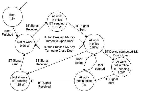
The status (or state) that is displayed can be one of the following:
- (At work, in office) Engineer is in the office,
- (At work, not in office) Engineer is not in the office, but eventually back soon.
- (Not at work) Engineer is not in the office and not at work.
Inputs are
- A button that registers working times. Pressing the button changes the state from the “at work” states to “not at work” or “not at work” to “at work, in office” or “at work, not in office”.
- The door knob to lock/unlock the door. If the door is not locked, the engineer is in his office, otherwise not in the office or (depending on the button) not at work.
Depending on the state or changes of the state, the following actions are performed:
- A message is sent to the central web server via WLAN which updates the state.
- A message is sent to nearby devices via Bluetooth which updates the state.
- The status is always displayed by an LED (green: in office, blue: at work, but not in office, red: not at work).
SystemC testbench and model template
For evaluation and comparison purposes, we provide a SystemC test bench. In the test bench, the SEAI system is instantiated and connected with:
- Inputs that are a sequence of changes of the status.
- The results of the power/energy estimation:
- The overall energy consumed over a simulation of a use case scenario.
- A sequence of <time, power> values that model the estimated (instantaneous) power consumption.
The test bench with the simple model instance shall serve as a starting point. It includes the basic structure and a template for the SEAI system. The template for the SEAI includes
- Basic setup for state changes and initial state definitions.
- Placeholders for the power consumption estimation methods to be created.
HW/SW details
In the following we give a brief description of the hardware. Actually, one likely might not need all details as we provide comprehensive measurement data.
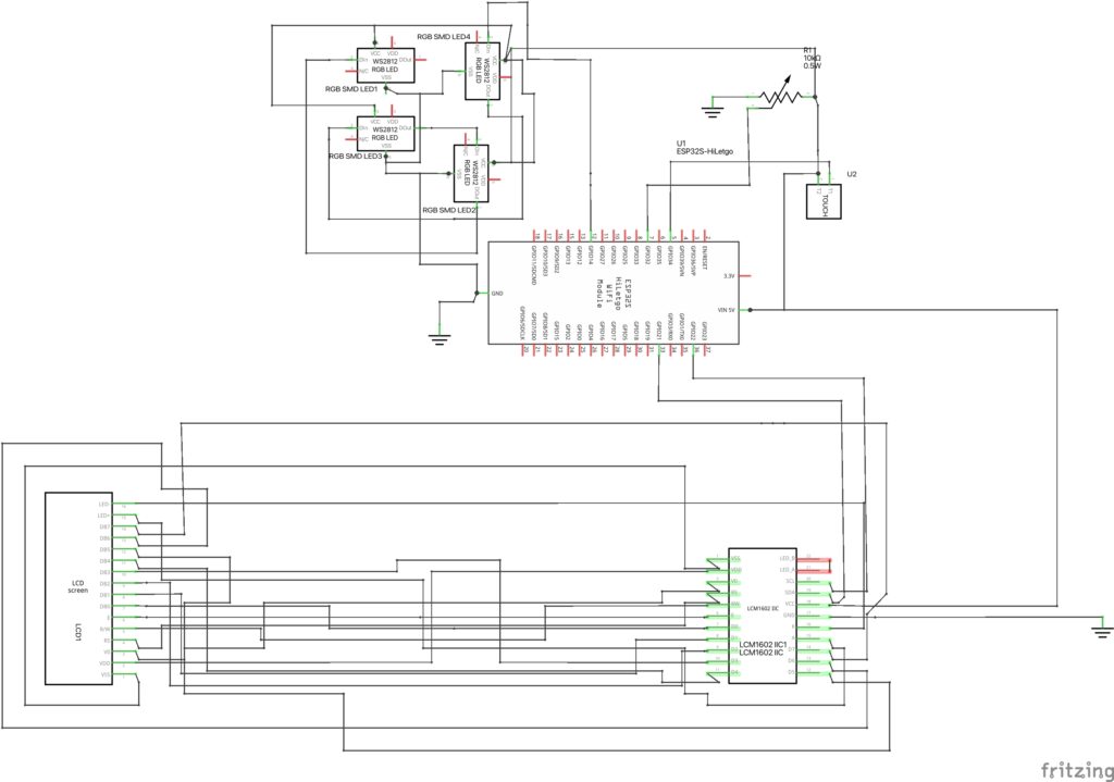
The implementation is based on the ESP32-WROOM-32D. It includes
- a central processing unit with memory,
- a Bluetooth transceiver, and
- a WLAN transceiver.
To the ESP board, we added
- four addressable RGB LEDs (PL9823 model), and
- an LCD display (2004B BL model) via I²C.
User inputs include a button and a potentiometer. The potentiometer, built into the door lock, changes the status when the door knob is turned. The button serves as an alternative input, allowing status changes based on the time recording system.
A schematic is shown below.
Videos
Data set for power estimation
The data set contains long-time measurements of the complete, above-given system.
Furthermore, a power state transition machine is given that might be the starting point for a SystemC implementation. Note that of course other solutions are encouraged, in particular using machine learning methods.